Analysis #1
A conveyor belt system was needed to transport the material through the heating element of the pyrolysis process. The conveyor belt needs to be slow enough that the full process can take place, but also able to have a smooth transition to and from other parts of the carbon fiber recycling system.

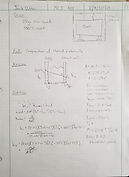
To contain the argon gas required for the pyrolysis project a shroud will be used around the oven. This shroud is metal thus there was a possibility it could heat up enough to burn someone. This analysis used a method similar to a double pane window in evaluated the temperature on the outer surface of the shroud during pyrolysis where the oven will be 500°C.
The desired result is to have the shroud heat up but not enough to cause harm to a human touching it. According to ASTM C1055 this temperature is 60°C (140°F). As long as the shroud does not reach that temperature it is sufficient.
Through analysis the final temperature the shroud will reach while the oven is running at 500°C is 30.6°C (87.1°F). This temperature falls below the standard; thus, nothing will be altered.
Analysis #4
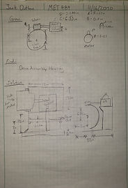
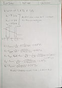
To achieve the required rpm to drive the conveyor belt (roughly 0.25 rpm) a gear train will be used to reduce the 850-rpm motor. To simplify the system a speed reducer will be used to reduce the rpm quicker and more efficiently.
A speed reducer had to be chosen so that it would function with the motor and reduce the rpm to a more reasonable number that would require only a few gears to completely reduce. Using the Nominal speeds and input rpm of the speed reducer, the final rpm found that the motor will reduce to is 17 rpm.
Analysis #5
The final step in achieving a 0.25 rpm output is a custom gear reduction. A spur gear assembly was analyzed using a triple reduction. An engineering tool of an excel spreadsheet which calculates stresses, dimensions, and required hardness was used to come up with the gear assembly.
Using a spur gear analysis, the gears tend to require a lot of hardness as they take a large amount of stress. Using this analysis, a worm gear reduction may be preferable.
Analysis #6
Similar to Analysis 5 the end goal in the gear drive is to have an output rpm of 0.25. Another possibility is to achieve this with a worm gear, rather than using spur gears. Another spreadsheet was used to calculate what kind of worm gear is to be needed.
From this analysis it is confirmed only a single worm gear reduction will be necessary and it is well within reasonable stress limits for common materials used for worm gears.
Analysis #7
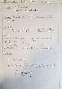
To use the above worm gear, design an output torque was required. The output torque is the rotational force required to move the chain conveyor system that will provide movement to the carbon fiber through the pyrolysis system.
Assuming an aluminum conveyor surface and transporting 5 pounds of matter through the system, the final output torque required was calculated to be 145 [lb-in]. This number is implemented into the spreadsheet used in the design of the worm gear assembly.
Analysis #10
Analysis #11
Analysis #9
Analysis #8
According to the textbook Machine Elements in Mechanical Design by Robert L. Mott, et al., the desired angle of wrap for a gear driven chain is 120° to avoid slippage (or 90° if the chain tension is properly kept tight). This analysis will calculate the angle of wrap for the driving gear located under the oven. To maximize the angle of wrap the gear is elevated above the driven gears and the horizontal distance is kept very low.
Upon analyzing the driving gear system, the angle of wrap was calculated to be 180°. This angle is very good for avoiding slippage as it is well above the 120° desired angle.
The conveyor system will be using a metal chain conveyor belt with 14 pinion gears spaced around the oven to drive and hold the chain. The locations of the pinion gears were analyzed and placed strategically to allow for clearances for the chain and working space, so they don’t scratch against the oven and wear out. The dimensions of both the shroud and the oven were used as the ideal scenario is to have the conveyor system fully inside the shroud with the driving gear attached to a shaft that leads to the gear assembly outside the shroud. An overall length of the chain was also calculated to provide a minimum amount to purchase for the final product. The following are the lengths and distances:
-
A = 12.75” [Center to Center]
-
B = 8” [Center to Center]
-
C = 2.25” [Center to Center]
-
D = 17.5” [Center to Center]
-
Overall Length = 68.75”
Knowing the amount of time, it takes to completely fill the volume of the shroud is useful to know spin up time for the system to be operating properly. To get the time it takes the mass flow rate from Analysis 8 was used in conjunction with its relationship to volume flow rate to calculate the time, in seconds, it takes to fill the shrouds volume.
The calculated time it takes to fill the volume is about 0.15 seconds. This means the system will displace a necessary amount of oxygen in under one second. With this information it is now confirmed that the primary choke on spin up time is the heating element reaching 500°C.
As per the pyrolysis process requirement Argon gas will be pumped into the system to displace the oxygen. Considering this, the mass flow rate must be calculated to determine the speed at which Argon enters the system and oxygen leaves.
Using a Bernoulli and Flow analysis the mass flow rate of argon from a pressurized tank is found to be 0.99 [kg/s] or about 2.18 [lbs/s]. This number is used in Analysis 9 to calculate the speed at which the shroud volume fills.
Analysis #14
Analysis #13
Analysis #12
A switch or timer needs to be placed in series with an internal wire to be able to control the motor without affecting the operation of the heating elements. As the original design has it the conveyor motor and heating are either both on, or both off.
To accurately depict where the switch will go in the wiring diagram, MultiSim was used to draft a copy and place the custom change into the diagram.
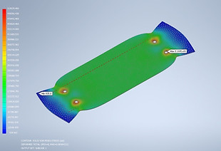
In the new design conveyor plates are attached to the existing conveyor system. These mild steel plates will be subjected to temperatures around 500C and must not yield, even after repeated and prolonged exposure.
The analysis was done using Inventor Nastran, a Finite Element Analysis system. Using the heat transfer as it fully covers the surface of the metal plate, the Von Mises stress can be found using this method.
The final stress found is 519,700 psi which is well under the modulus of elasticity of mild steel (E=29,000 ksi)
The assembly that is used to drive the conveyor system (motor, speed reducer and worm gear assembly) take up a large amount of space, and when moving pose a safety hazard. To contain everything in one place and prevent accidental injury a box will be made custom to house everything. Being made of aluminum sheet, this box will cost little in terms of raw materials.
The use of SolidWorks was employed with this analysis to ensure that the pieces fit with enough clearance to guarantee no scraping of parts.
Analysis #2
Analysis #3
During the pyrolysis process the resin that is epoxied to the carbon fiber will be vaporized. There is only a limited amount of mass possible to heat at one time, as overloading the system would cause resin to not fully vaporize.